• gameDoggo

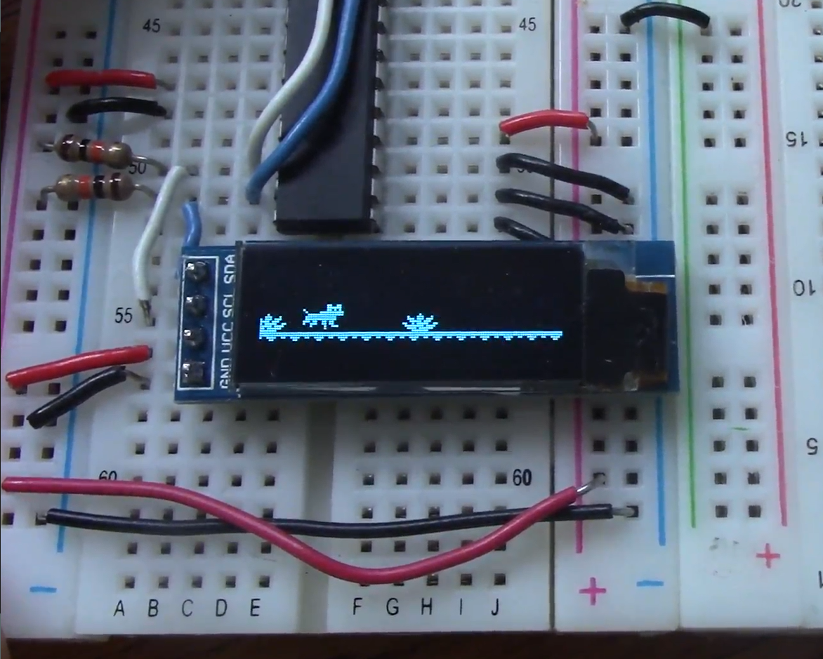
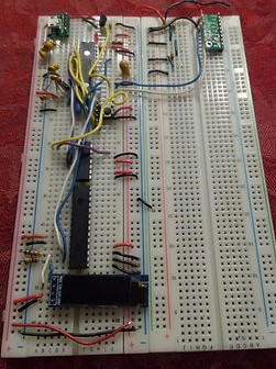
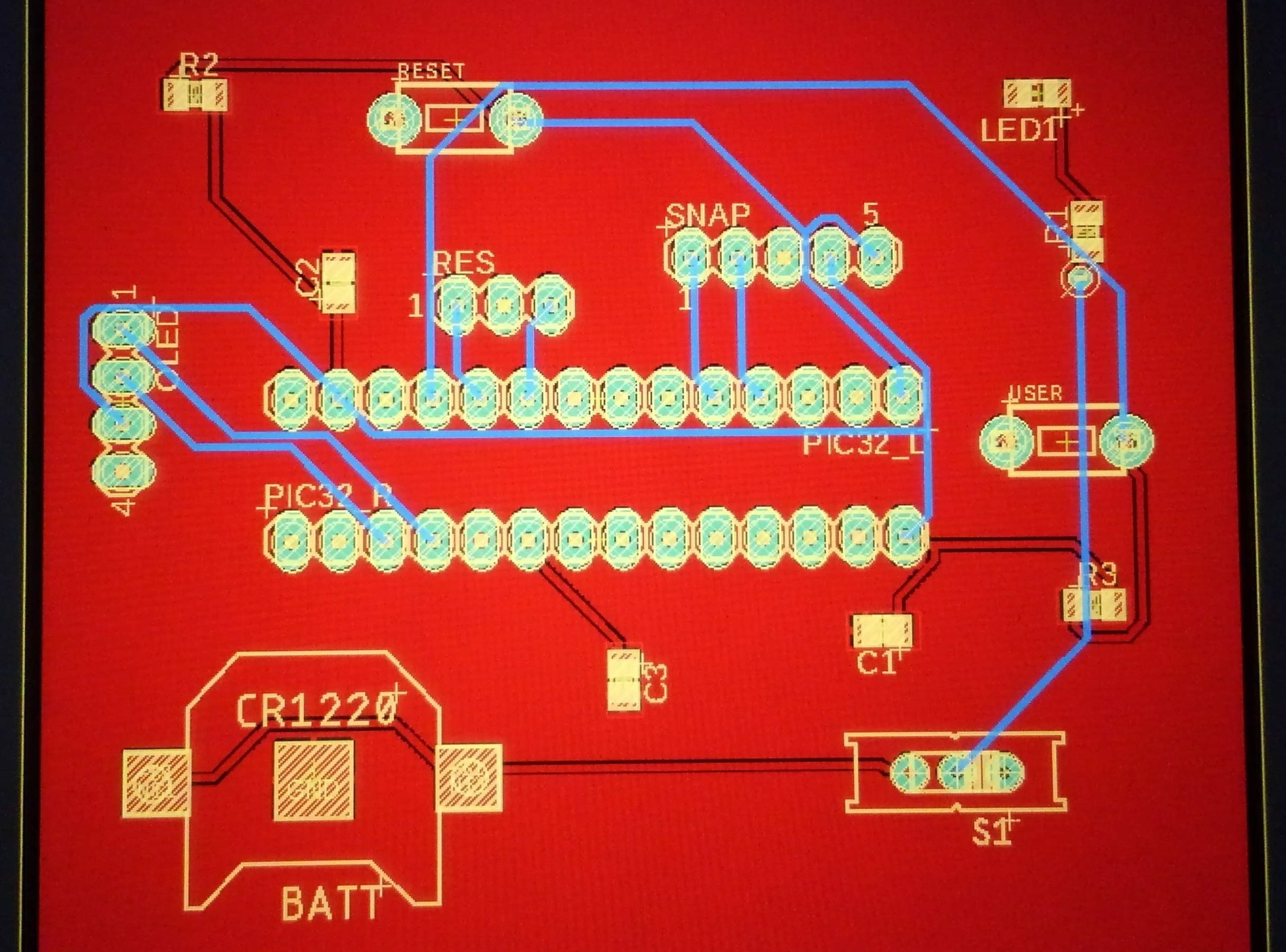
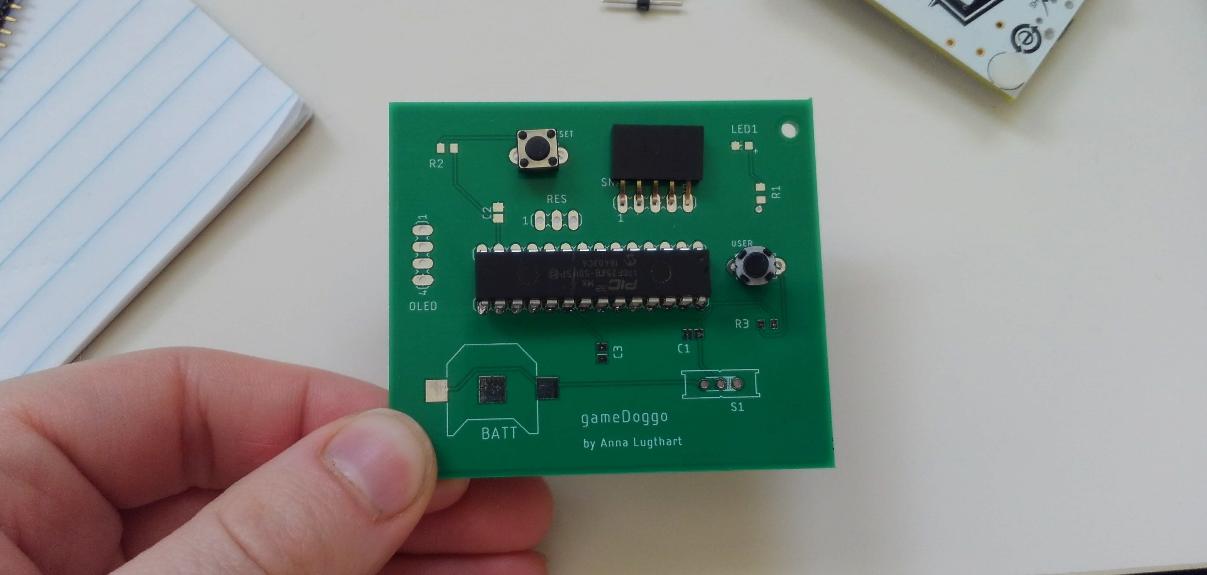
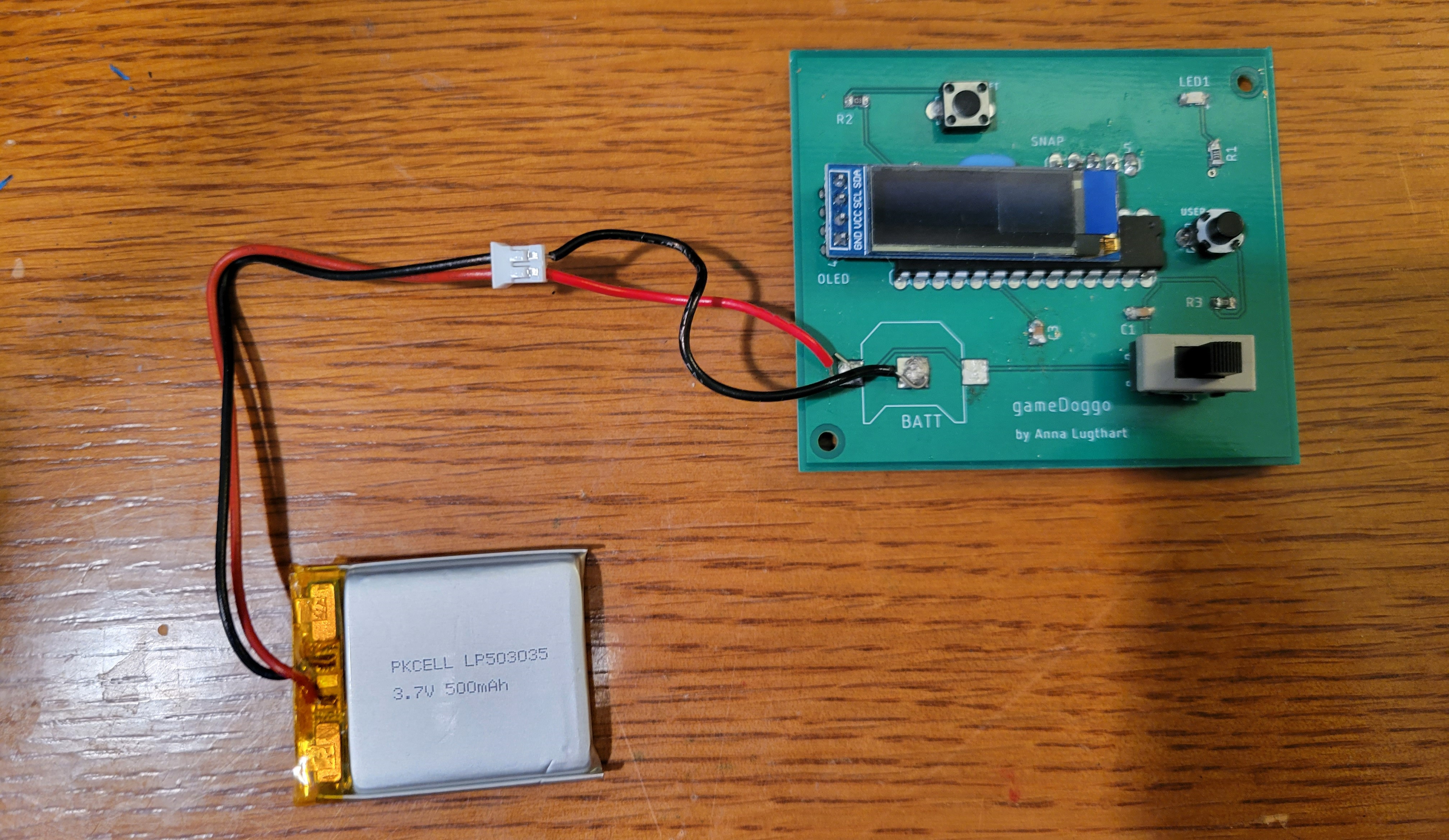
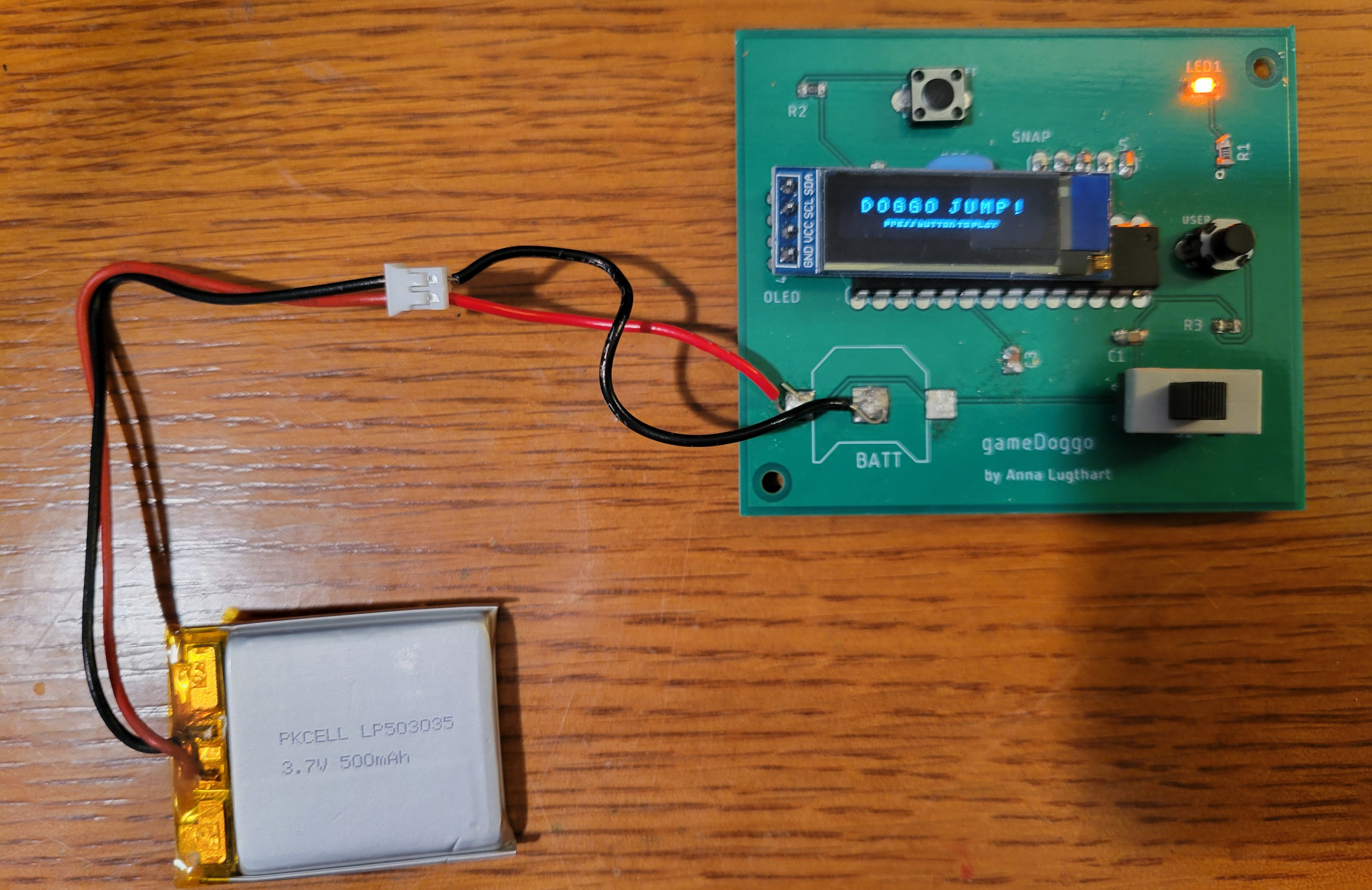
    During the Smart Watch Project, which I made for a mechatronics class, I went beyond the scope of the project to design and code my own video game that could run on the board.

    The game is coded entirely in C, runs on a PIC32MX170F256B microcontroller, and outputs to a 32x128px OLED display.

    See code here!
    a screen on a breadboard displaying a running dog

    The game, wired on a breadboard

    The game originally ran on a breadboard and was powered by a USB. The circuit contained many components, including a DAC, gyroscope, and additional I/O that were useful for the smart watch, but not necessary for the game.

    a circuit wired on a breadboard

    The smart watch circuit, wired on a breadboard

    I learned Autodesk Eagle so I could design a custom printed circuit board (PCB) for the game.

    In order to save space, soldering time, and money, I kept only the microcontroller, OLED display, buttons, on/off switch, and other necessary components.

    • a computer diagram for the game PCB
    • a PCB with some components set in place

    Game PCB design (Top) and PCB with some components in place (Bottom)

    After soldering the components, I noticed an issue. I had originally planned on powering the board with a CR1220 battery, but it didn't provide consistent (or long lasting) current.

    I purchased a 500mAh rechargable Lithium Polymer (LiPo) battery and surface soldered two wires onto the board for an attachment point.

    • a game PCB powered by a LiPo battery, off
    • a game PCB powered by a LiPo battery, on

    Game PCB powered by a LiPo battery, on (Top) and off (Bottom)

    The game runs great now, but still has room for future iterations. Improvements include using fewer through hole components, squeezing components closer together for a smaller footprint, and 3D printing a case to hold everything together and make it look more like a game console.

    Game demonstration

    a decorative dingbat